_____Stu's___Dungeon__
Joyful Honda
Treasure
Lesson Room Cabs
In the beginning
2
3 4 5
6 7 8
9
10 11
12 13 14
15
Jointer1
Jointer2
Router
Table1
Router Table 2
The Doors
Do
Pa
Give Me A Brake
Cyclone
Cyclone 2
Cyclone
3
Cyclone 4
Liquor
Shop Reno Tenjinsama Shrine Tree Tour
Beer Shelves
Wine Shelves
Five Cuts
Drill Press <NEW
DoPa 2007 <NEW
Turning
Jean Francious Escoulen
Eli Avisera Demo Day One
Eli Avisera Day Two
Lathe Stand!!
Turning
Roughing
It
Sharpening Station
Bowl Blank Processing
Captured Hollowing Rig
<NEW
Logging In Tokyo
Woodlot Woodlot
2006 Woodlot
3 Woodlot 4
Chainsaw Mill
Chainsaw
Mill Mk II
The Cyclone
I bought a Dust Collector (DC) a while back, it is a big unit,
and while not new,
it sure works well at collecting the dust.

My daughter Mizuki and me with the newly arrived BIG DC
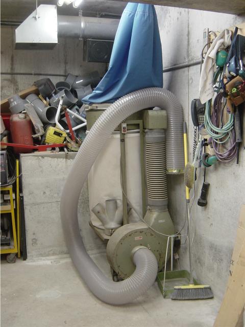
The DC in it's place.
The problem is the filter bags do not work very well, there is
a lot of very fine dust that gets by the bags,
I end up with a very fine talc like coating of dust EVERYWHERE.
This dust is the WORST kind of dust to be breathing in all the time.
So what do I do?
The solution, after a lot of research on the net, is a
cyclone.
If the cyclone is built correctly, then it should remove all the fine dust and
provide a lot of suction at each tool
Partly to accomplish this I've run 6" pipe and flex hose to each machine,
no reductions down to 4" as is usually done.
My main source of information for this has been the WebPages of Mr. Bill Pentz.
Cyclone Basics In spite of what some would like us to believe, dust collection cyclones are simple tanks with no moving parts and have been used for dust separation for over seventy years. They are made up of just a few parts, an air inlet, an outer cylinder, an air outlet, and cone with dust chute that connects to a collection bin with flex hose. Dirty air comes in through an inlet and spins quickly around. This spinning throws the heavier particles outward to the cyclone walls. Airflow on the cyclone walls is slowed by friction. Particles get trapped in the slower moving air then gravity pulls them down. As the air continues to spin it slows and drops downward. The cone on the bottom of the cyclone forces that slowing air to keep the particles pressed tightly to the walls. Those particles continue to slide downward and eventually exit out a dust chute into the collection bin. The dust chute is sealed tightly to the bottom of the cyclone with no air leaks to stir up the collected dust. At a certain place inside the cyclone called a neutral point, the spinning clean air reverses direction and comes up through the center of the cyclone then exits through the cyclone outlet. In spite of what some would like us to believe, dust collection cyclones are simple tanks with no moving parts and have been used for dust separation for over seventy years. They are made up of just a few parts, an air inlet, an outer cylinder, an air outlet, and cone with dust chute that connects to a collection bin with flex hose. Dirty air comes in through an inlet and spins quickly around. This spinning throws the heavier particles outward to the cyclone walls. Airflow on the cyclone walls is slowed by friction. Particles get trapped in the slower moving air then gravity pulls them down. As the air continues to spin it slows and drops downward. The cone on the bottom of the cyclone forces that slowing air to keep the particles pressed tightly to the walls. Those particles continue to slide downward and eventually exit out a dust chute into the collection bin. The dust chute is sealed tightly to the bottom of the cyclone with no air leaks to stir up the collected dust. At a certain place inside the cyclone called a neutral point, the spinning clean air reverses direction and comes up through the center of the cyclone then exits through the cyclone outlet.Although just about any cyclone design will separate the heavier particles, it takes quite a bit of work to build a design that will efficiently separate off most of the finest particles so they don't clog our filters. Any air turbulence from these parts will dramatically increase resistance and significantly reduce fine particle separation efficiency. A smooth inlet is needed to carefully start the air stream right on the side of the cyclone. The smaller the diameter of a cyclone, the faster the air must move and the better the separation. Likewise, the smaller the cyclone diameter the larger the blower needed to overcome the resistance. It takes more work to push air in smaller circles. Cyclones with longer cones provide better the fine material separation. Likewise, longer cones create more resistance because the air has to run more revolutions. You can compute a near ideal cone length for maximum separation efficiency based upon air speed, inlet, and cyclone diameter. Finally, the larger the cyclone outlet, the less resistance and slower the airflow making for much finer the separation.
|
There is a company making Mr. Pentz's cyclone out of clear
plastic, they are really cool
The company is called Clear Vue
Cyclones, you can see a really cool video of the cyclone working by right
clicking and selecting "Save As" from "THIS"
link (the file is about 1.3 Mb)
Know that you know how a Cyclone works, I'll get into showing you what I've done to build one, as buying one from the US and having it shipped here would cost WAY too much money.
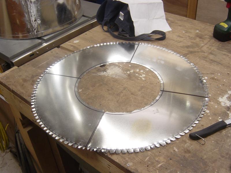
The first major hurdle I have it finding the galvanized sheet
metal, I did find it at my favorite DIY center,
Joyful Honda, but the size is kind of small, about 3' x 6'.
This means that I'll have to make the cone part of the cyclone from two pieces
of sheet metal, what a pain!
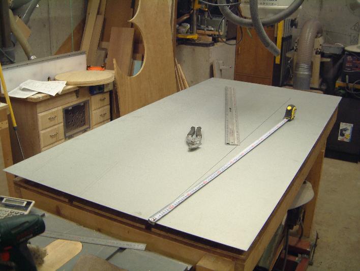
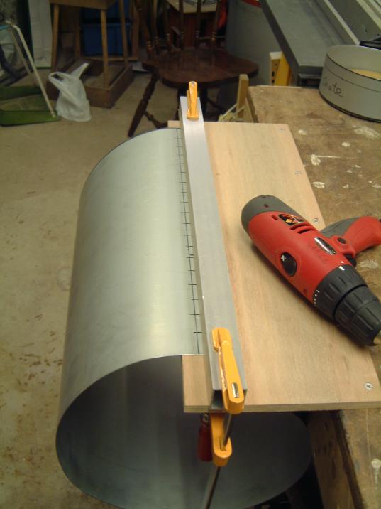
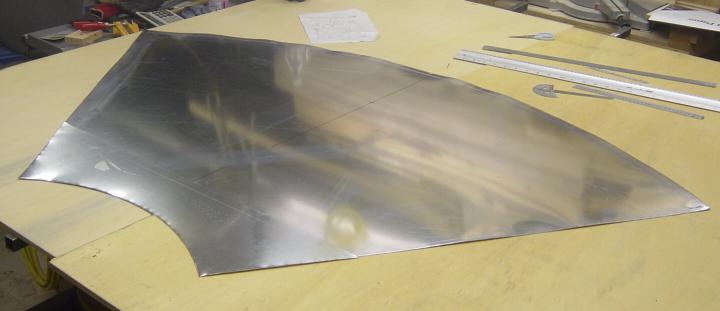
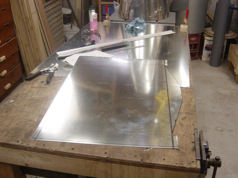
Here I have the sheet metal on the bench, with my tin snips and some rulers etc.
The first cut done, I'm underway!
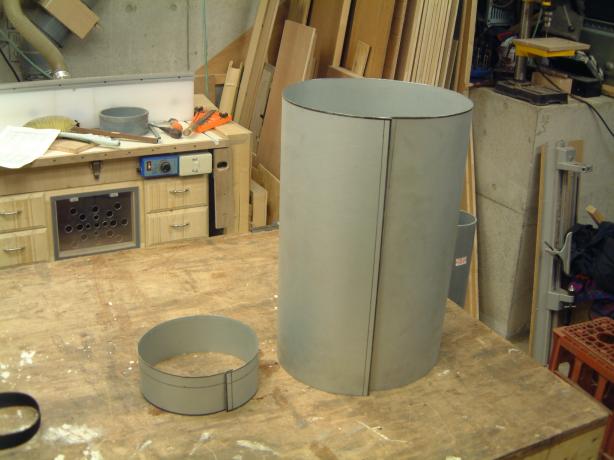
There is the second cut done, this will be the main cylinder of the cyclone.
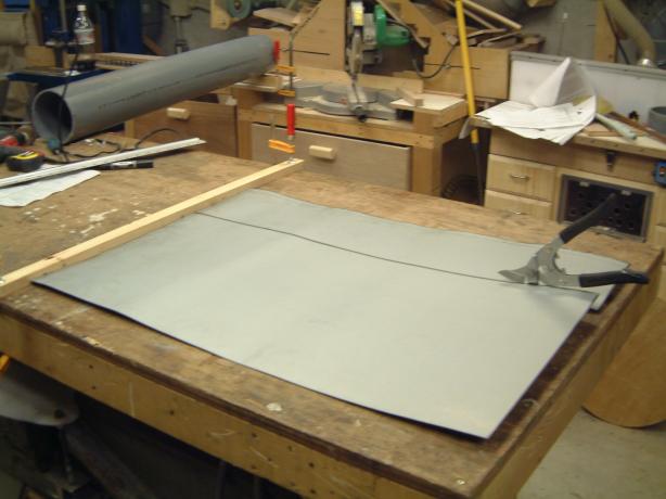
Something that I did that helped is to clamp a blocking board to the bench, this
way the sheet metal could be pushed into the board and made sliding the snips
forward much easier.
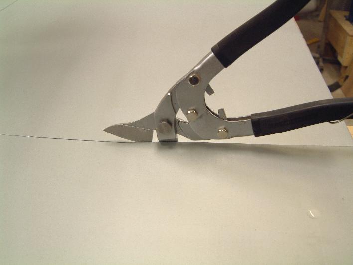
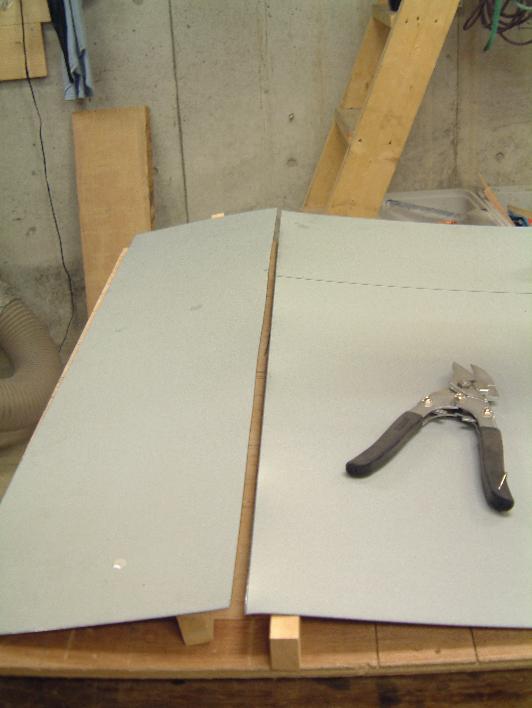
These are the tin snips I'm using, they worked really well
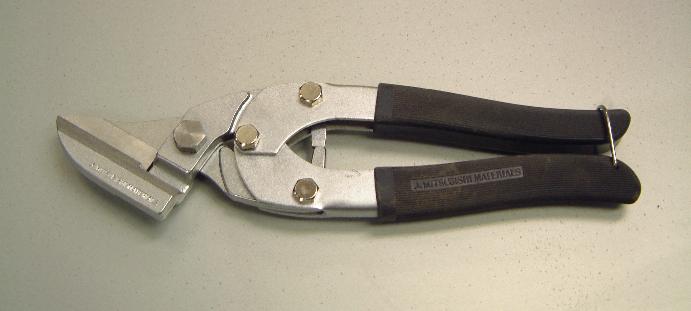
Not cheap, but they sure work well!!
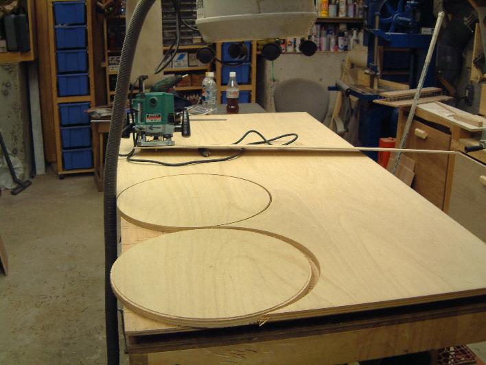
I need to make some templates to hold everything round while building the
cyclone.
Here are the first circles I cut, they are 18", don't ask me why I did
this, my cyclone is NOT an 18" unit!!
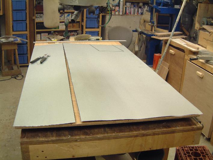
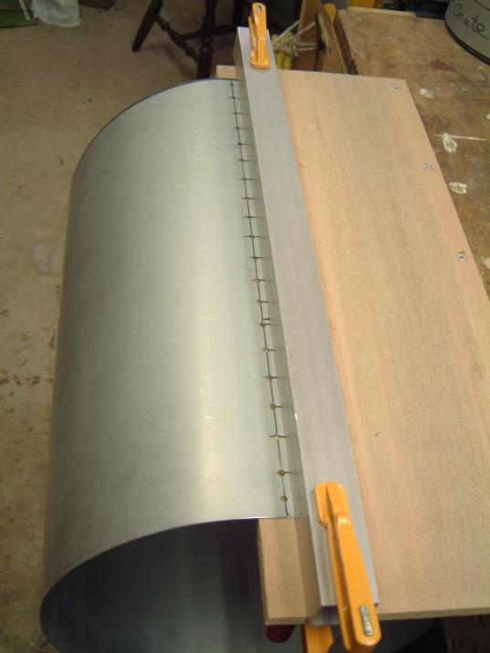
Using Mr. Pentz's advice, I roll the sheet metal over a 6" piece of PVC
pipe, this is a very good way of making the sheet metal conform to the shape
needed.
Here is the steel wrapped around the 18" templates.........Whoops, wrong
sized templates!!!
With new correctly sized templates, things are looking better
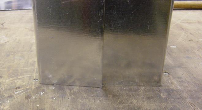
Through careful forming I was able to get almost no gap at the joint,
this makes putting the main cylinder together much easier.
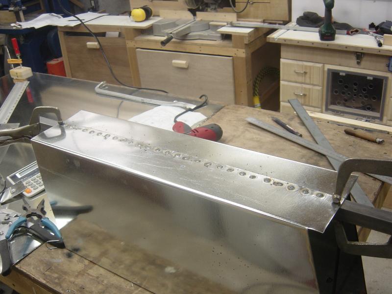
To stitch up the cylinder I've opted for using my MIG welder,
I'll drill holes and then button hole weld it.
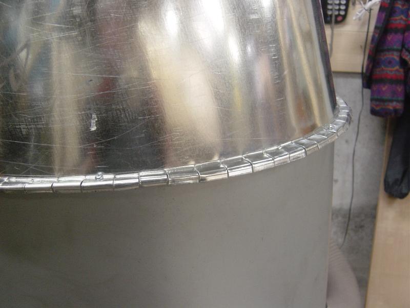
All drilled, now I clean it up, remove any burrs and lightly sand it.
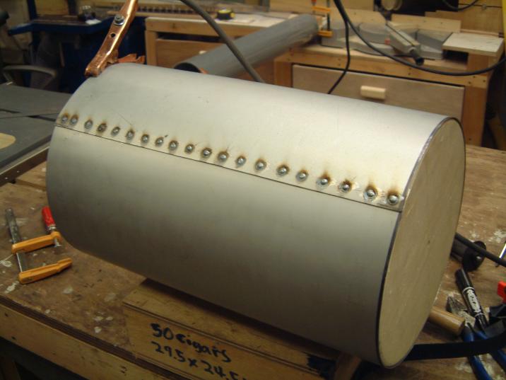
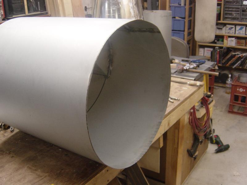
There it is all welded up.
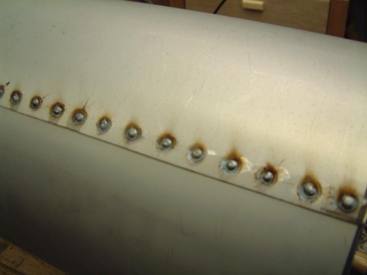
Worked well, and was quick and easy.
I got decent penetration, without blowing holes in things.
Ready to go!
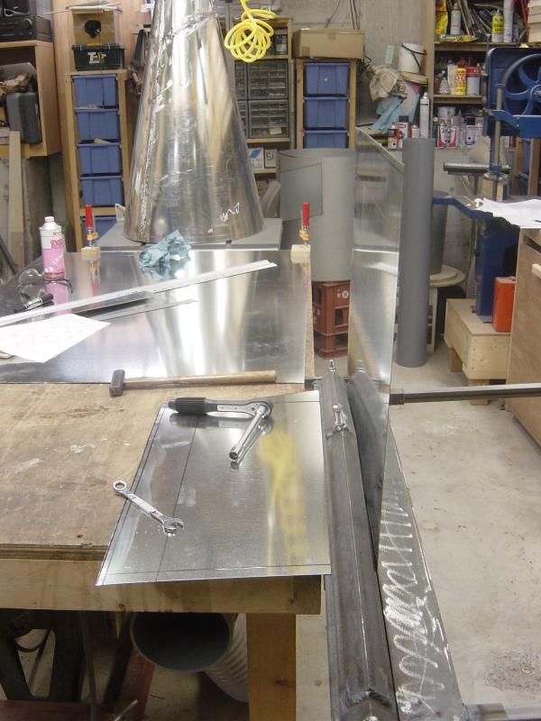
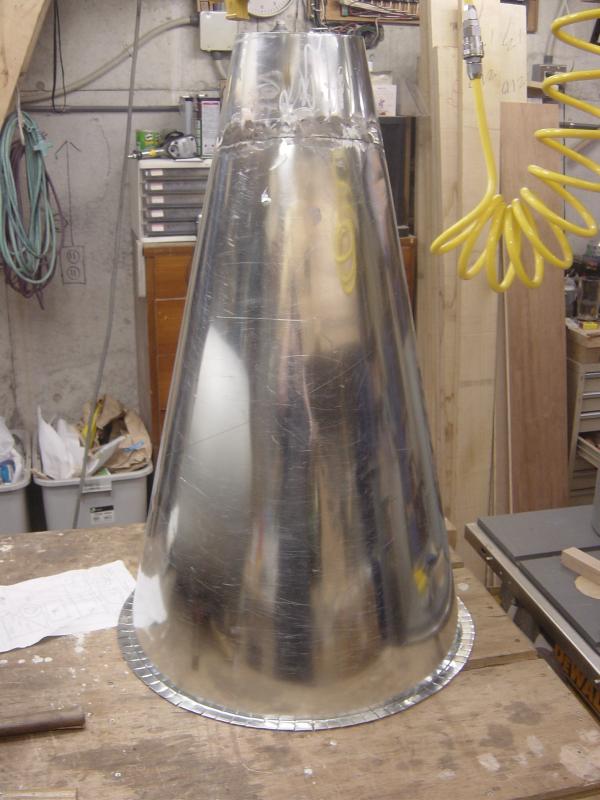
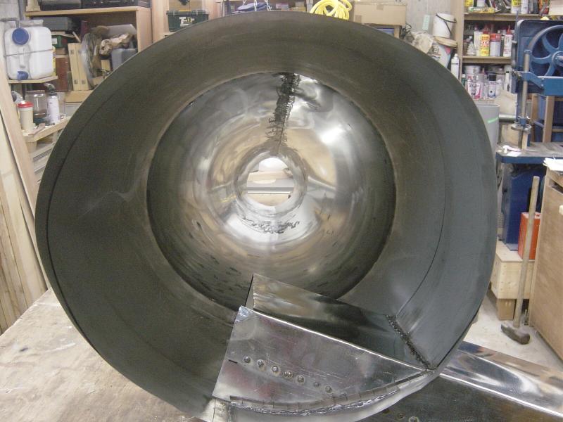
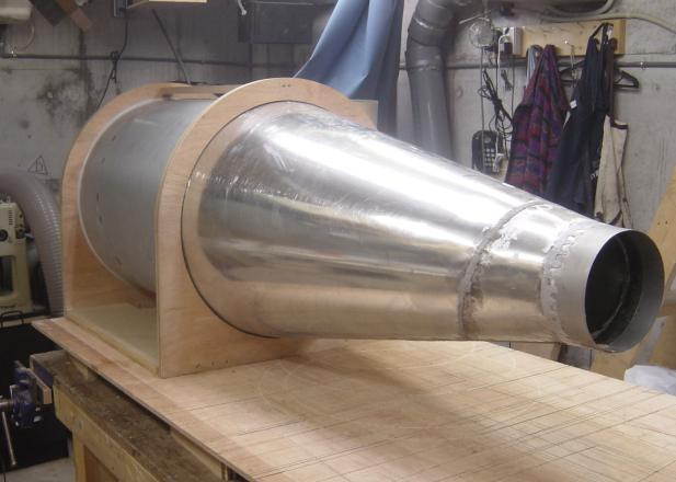
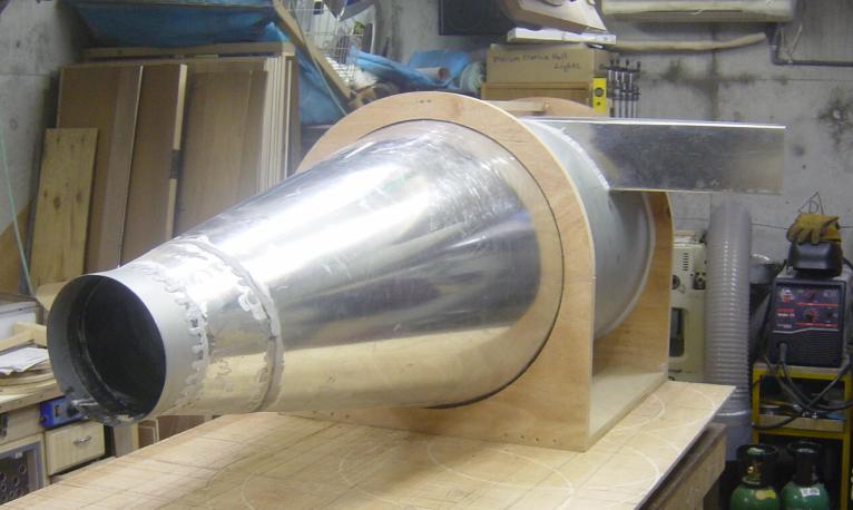
On To The Cone
The cone part of the cyclone has turned out to be the most
difficult.
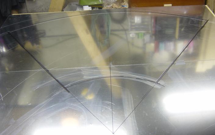
I had to use two pieces of sheet metal to get the size I needed, the lay out was
a chore.
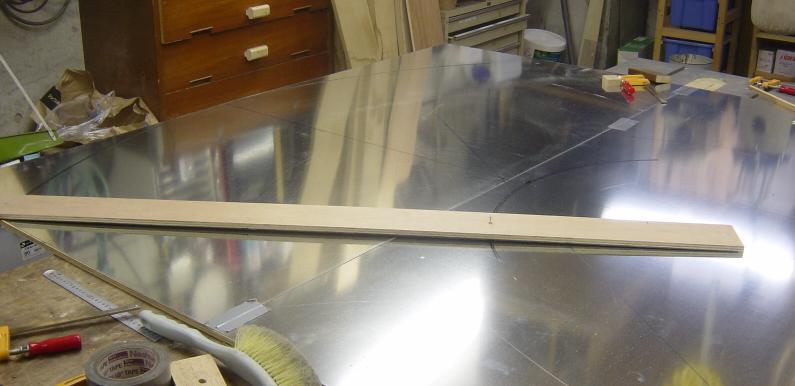
Here I am drawing the large arcs for the cone, I used a piece of plywood and
some nails, worked well.
Lots of very precise measurements here, some serious head scratching but I got
it done.
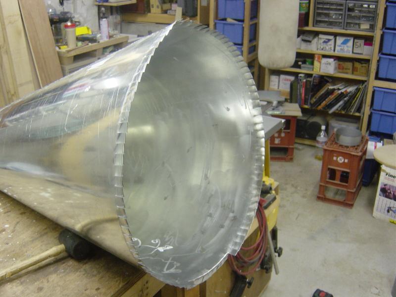
There are the two cone pieces all cut out.
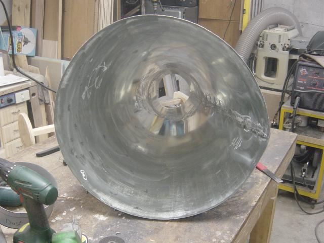
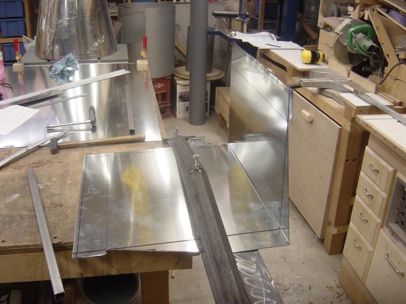
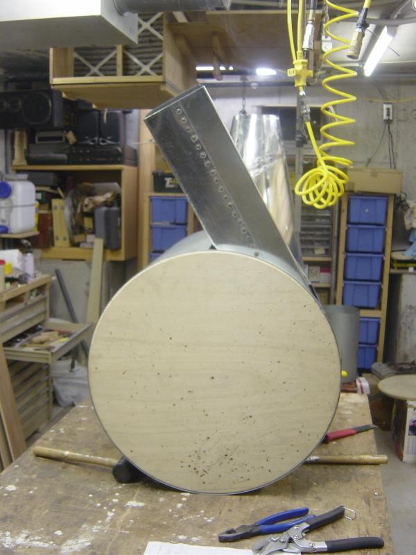
All welded up, but it needed a bit of tin basing to get it round.
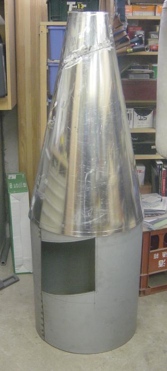
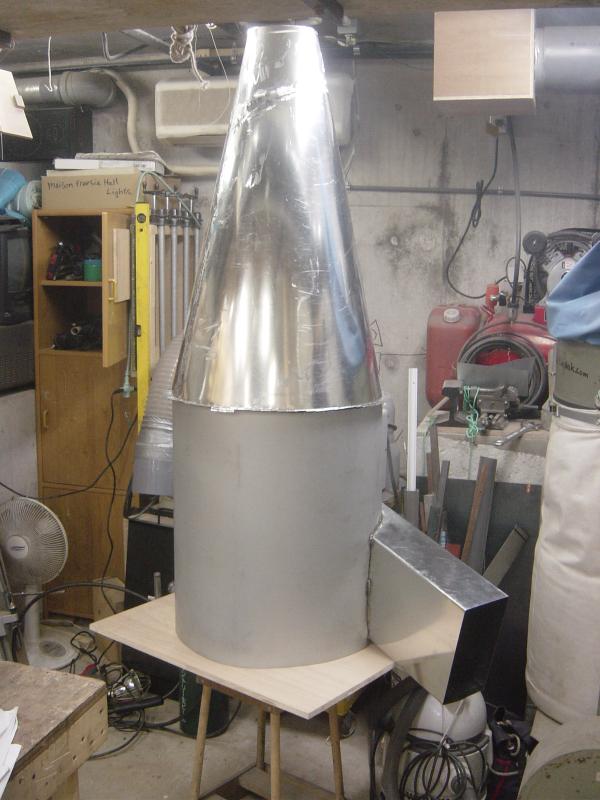
Here is the cyclone all welded up sitting on the upper cylinder, just to test
the fit
(I know the upper unit is upside down!)
Next I made the outlet tube, on the right, and the dust chute, which goes at the
very bottom of the cone
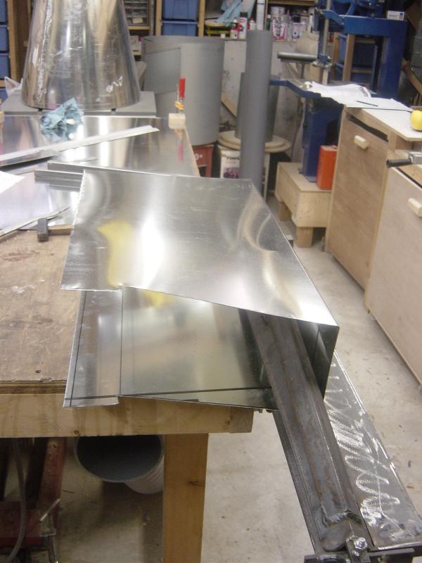
The next part I had to make is the inlet, it is not round, but rectangular in shape.
To make things easier, and as I know I will use it again and again, I made a sheet metal brake
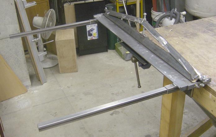
Give
Me A Brake <- if you click this link you can see the creation of this
unit.
Here is the inlet all cut out ready for bending
Using my new snazzy brake, here is the first bend
Getting ready for the second bend.
The second bend done (the adjuster on the clamp was a bit in the way)
There is the third bend finished
And the fourth bend.
Here is the inlet all bent up, nice and straight!!
A close up
All set up to do my MIG button hole welding again
There it is all welded up
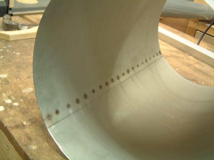
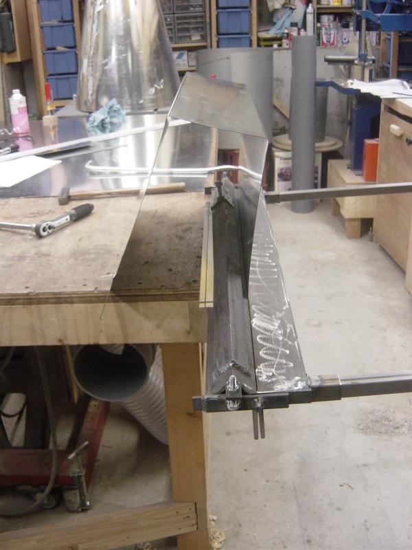
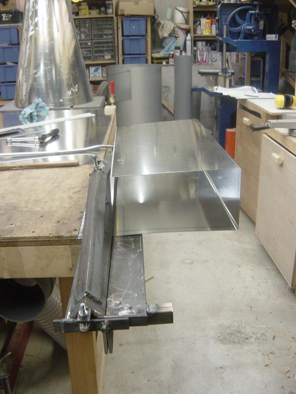
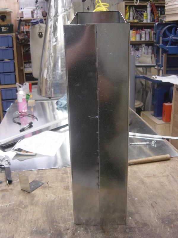
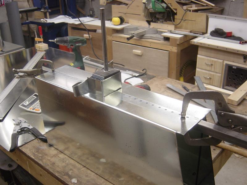
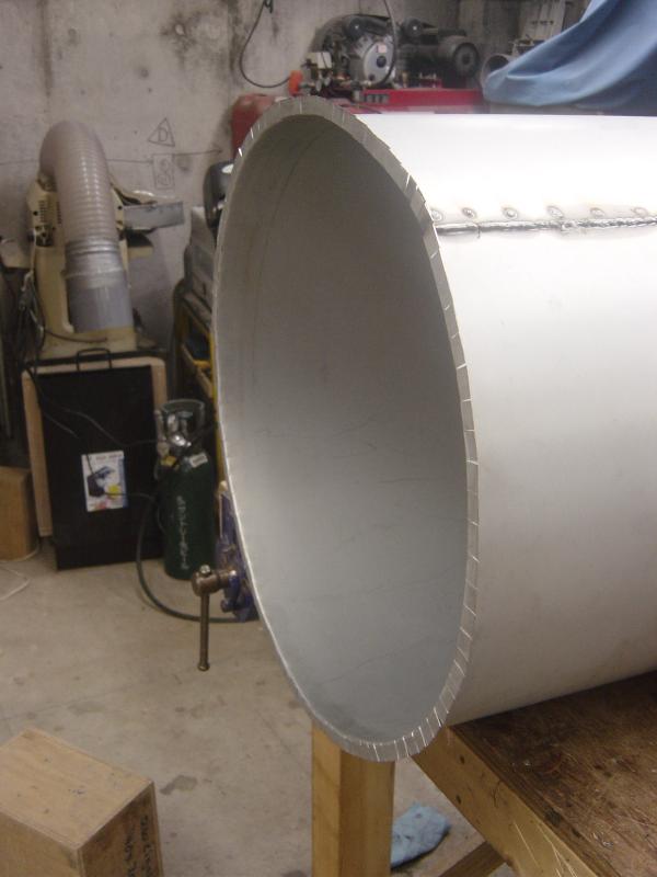
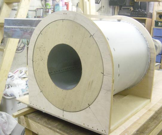
Here is the first try at inserting the inlet into the main cylinder
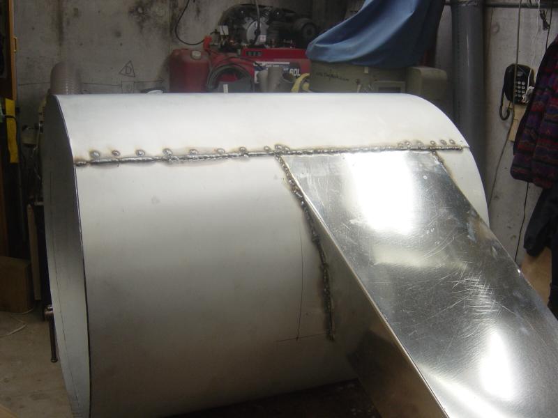
There it is welded in place.
I'm now cutting and bending the tabs on the cone and the main cylinder, this
took a lot of time and effort!
Here is the cone with all the tabs cut and bent, ready to join the main cylinder
Cutting the tabs on the main unit
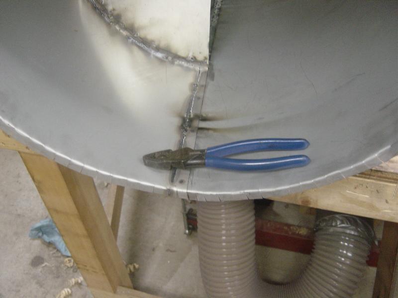
Here you can see the tabs bent out. I used my Kline linesmen pliers, the worked
very well
All bent out
Now I have to join the two units. I put the template rings back into the main unit and the cone, I left the template ring in the cone about 1/4" proud, and the then put the template ring in the main unit about 1/4" into the cylinder, this way the template rings will line the cone and the main cylinder up (I hope!)
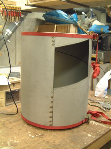
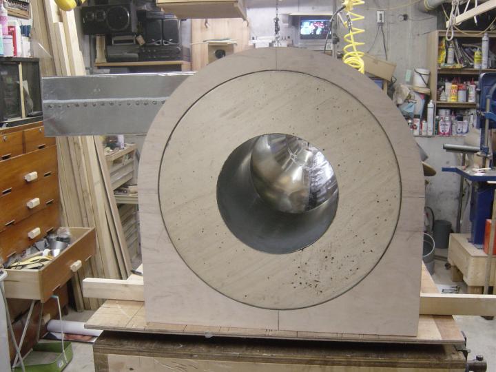
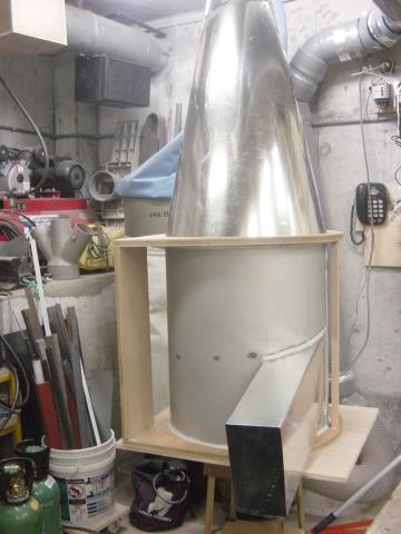
The cone and the main cylinder units together at last!
The tabs on the cone are slightly longer than the ones on the main cylinder, so
when everything is lined up, I bent the longer tabs over the shorter ones, again
I used the Kline pliers.
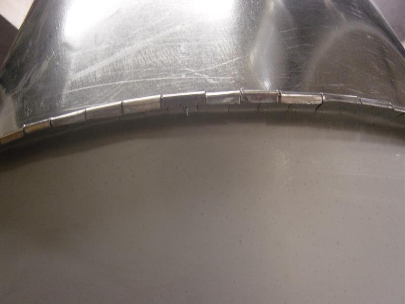
Looking up at the bent tabs, the ones on the left have been "tapped"
over ,
while the ones on the right have not yet been tapped over.
I found that tapping with a medium sized hammer to be a very quick and easy way
to do the second bend.
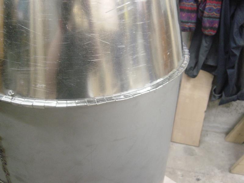
Here you can see on the left, the tabs have been tapped over, and on the right,
they have been crimped.
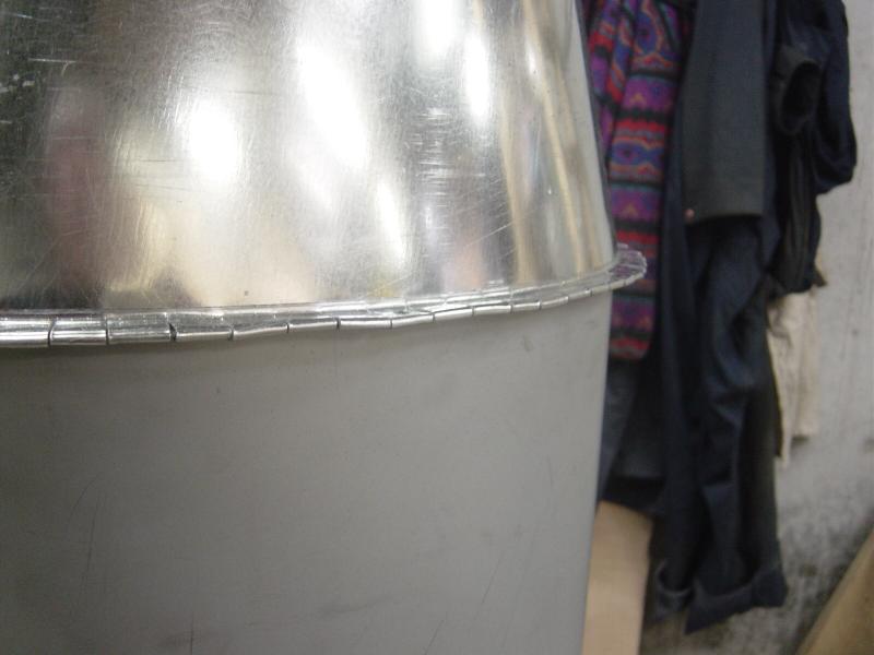
A closer look
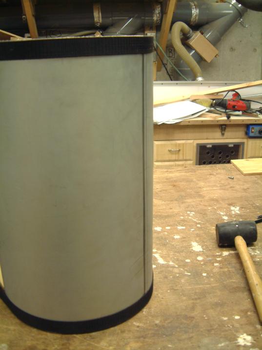
Everything all crimped together, ready for some welding and sealing.
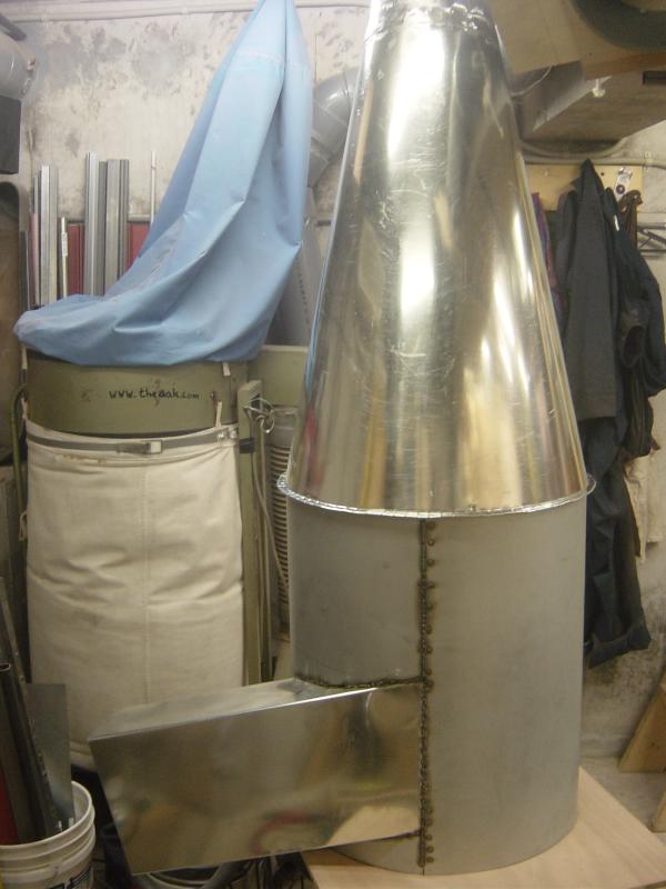
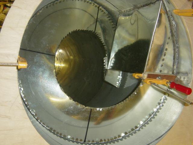
The next thing to do is move this now LARGE unit to the work bench and take out the template rings, then I have to cut out and install the air ramp.
Here is the air ramp with the outside tabs cut,
This sure was a lot of work!
Now I have to install this air ramp and then do some more tin work, as I have to make a transition from the round &2 pipe to the rectangular inlet.
Here is the top down view of the air inlet, the air ramp is not yet installed.
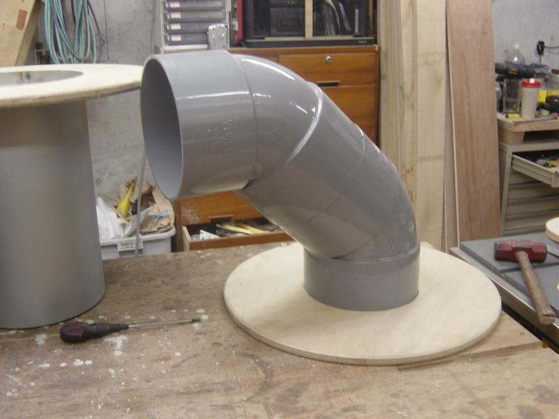
Because the motor and blower unit is so tall (50cm) I thought I would put the
blower on the side,
but the two 45s together end up being taller than the motor blower unit!
I'm going to try to cut down the two 45s so that I can get the extra height I need.
On to the Air Ramp
The air ramp is important in the whole scheme of things, so I
wanted to get it right,
but I tell you, so far I'm just about pulling my hair out!
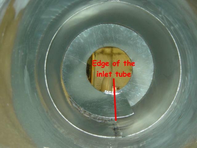
I'm starting to think that I may have made a big boo boo here, maybe the
"Inlet Tube" is not supposed to be all nice and square, but more of a
squished rectangle?
Mr. Pentz's plans are not clear on this point (well to me they are not, but I
could be missing something, would not be the first time!!).
I'm
also thinking that the bent "tabs" on the air ramp may not be the best
idea,
as they make the ramp hard to manipulate, bend and stretch.
In spots, there is as much as a 1/4" gap!
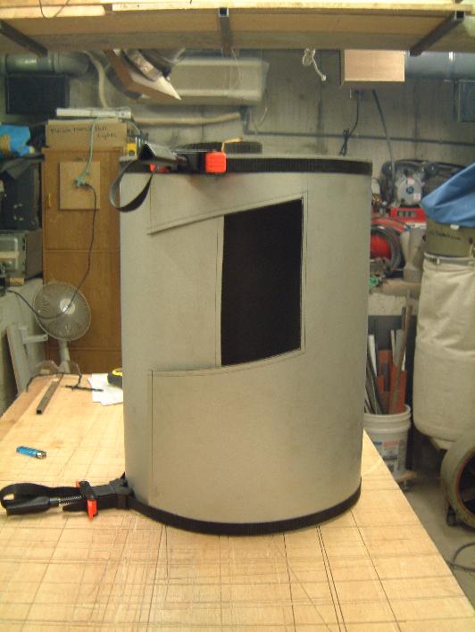
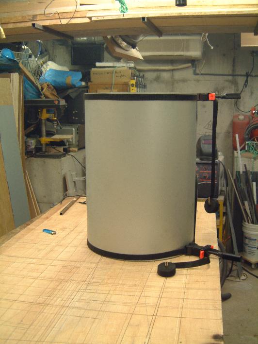
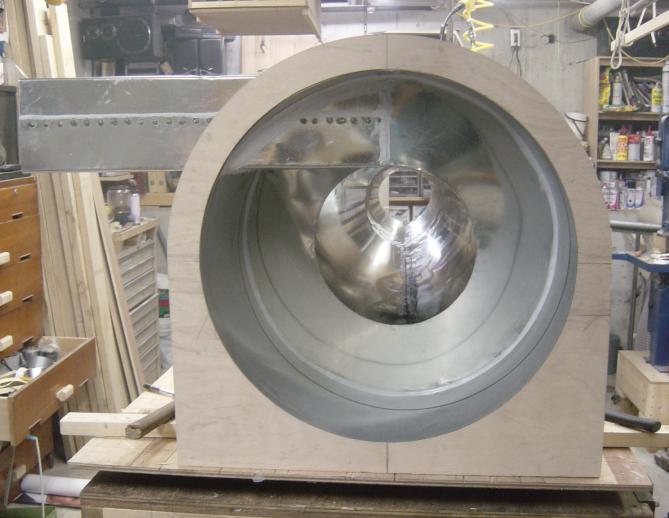
The cylinder is nice and round, the cone on the bottom is keeping it round,
and the outside ring is keeping the top nice and round too.
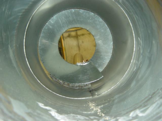
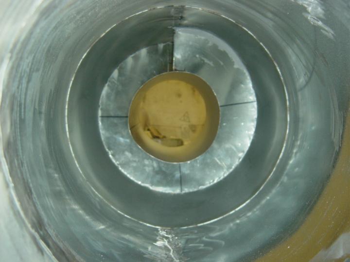
From inside the cone, looking from the top to the bottom,
from here it looks OK, but it is not....
Even with the slight gap at the top, there is still a lot of extra
material......?
I really don't want to bug Bill Pentz about this, the guy seems stacked up with things to do, but I might just have to e-mail him about this.....
OK I got it figured!
I cut the tabs off and then fit the air ramp, it fit very well!
This pic is from the top down without the center air outlet
cylinder in place.
The gray line is the caulking, I also spent an hour or so caulking the
whole cyclone.
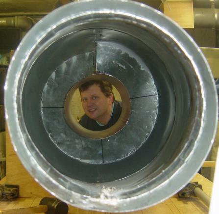
This is looking up through the cone, the center outlet cylinder is in place in
this shot.
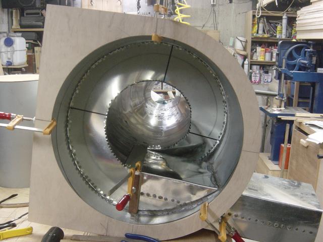
Here is the view from the top with the top inside and outside rings in place,
and the center outlet cylinder.
![]()
I'll still have to do some tin bashing, but the Transition is all but done.
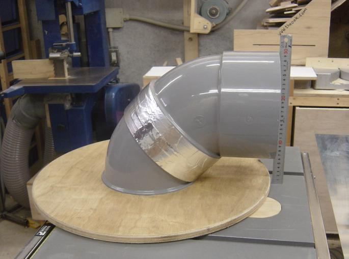
I cut down the flange area of these two 45s make the whole unit shorter, shorter
by 20 Cm!!
Here is how it looked before I cut it down...
This page has become so long, I've made a new page, Cyclone 2....