_____Stu's___Dungeon__
Joyful Honda
Treasure
Lesson Room Cabs
In the beginning
2
3 4 5
6 7 8
9
10 11
12 13 14
15
Jointer1
Jointer2
Router
Table1
Router Table 2
The Doors
Do
Pa
Give Me A Brake
Cyclone
Cyclone 2
Cyclone
3
Cyclone 4
Liquor
Shop Reno Tenjinsama Shrine Tree Tour
Beer Shelves
Wine Shelves
Five Cuts
Drill Press <NEW
DoPa 2007 <NEW
Turning
Jean Francious Escoulen
Eli Avisera Demo Day One
Eli Avisera Day Two
Lathe Stand!!
Turning
Roughing
It
Sharpening Station
Bowl Blank Processing
Captured Hollowing Rig
<NEW
Logging In Tokyo
Woodlot Woodlot
2006 Woodlot
3 Woodlot 4
Chainsaw Mill
Chainsaw
Mill Mk II
The Phoenix

Building a Bandsaw
OK, I got tired of waiting for a good 14" bandsaw to show
up on auction here (I've been looking for TWO YEARS)
so I'm going to build one.
A buddy in the US, Steve Clardy, had his roof on his shop
collapse over the last winter,
his 14" bandsaw took a direct hit, breaking the frame of this cast iron
saw.
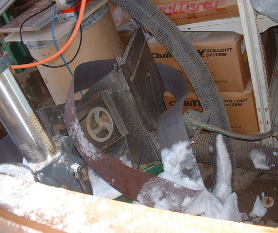
Steve' poor busted saw, you can see where the neck broke off at the green light
there on the right lower part of the pic
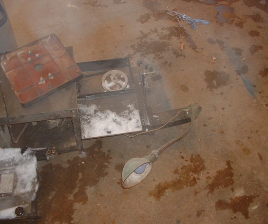
A better pic of the busted frame
We shall call the new saw "The Phoenix"
Well after Steve had rebuilt his shop's roof, with the help of
a bunch of different groups of people at various woodworking sites,
I got to wondering about the "Parts" from his busted saw, were they
serviceable, did he still have them?
Steve, being the good guy that he is, sent the parts to me for the cost of the shipping
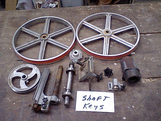
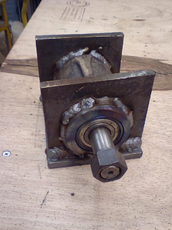
Here is the package of parts, we have the two wheels, the main pulley from the
back of the bottom wheel,
the bottom shaft, the top tension/tracking adjuster mech, the bottom blade
guide, the top blade guide,
and the bearing saddle from the bottom casting, that Steve "Busted"
out for me.
Also tucked into the box of bits.......
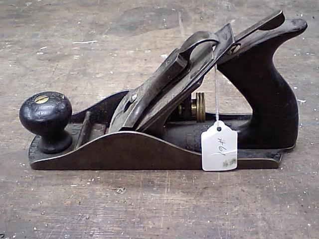
A nice Bailey plane, a gift from Steve!
OK on to the build.
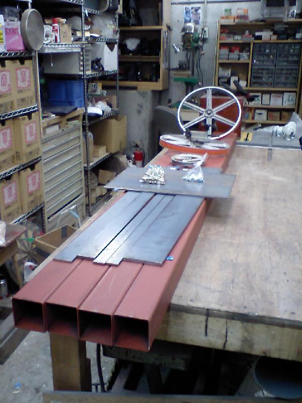
I bought a bunch of steel and now I have to cut it all up and build a saw.
The square tubes are 7.5 cm square, and they are structural steel for buildings, should be good.
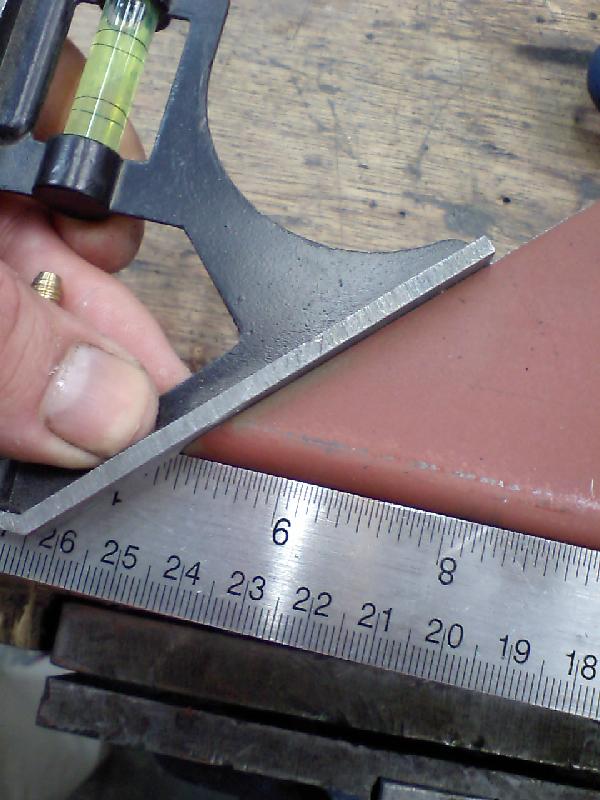
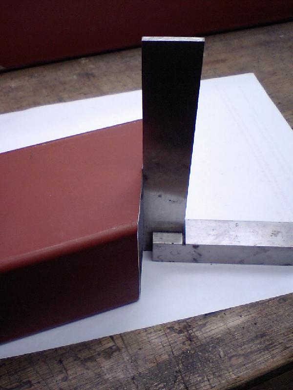
OK, I got the 45 right on the cuts, but the faces are not quite square.....
out by about a millimeter.
No problem, that is what 4" angle grinders were invented for!
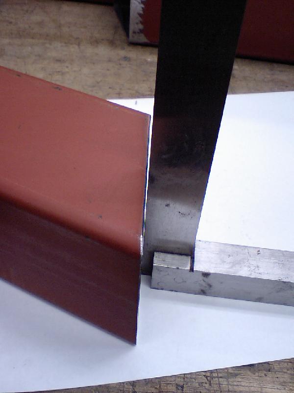
I've flipped the piece so the long edge is now up, and I've ground a slight
bevel on the edge.
This will be my "Grind to" line, once the bevel is gone, I'll check
the face for square.
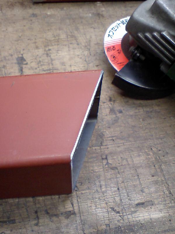
A little grinding and the face it dead on.........
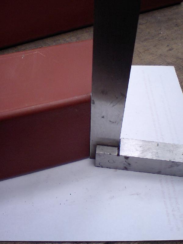
So is the edge. By doing this, the whole frame lines up just about perfect, and
I can get nice tight welds.
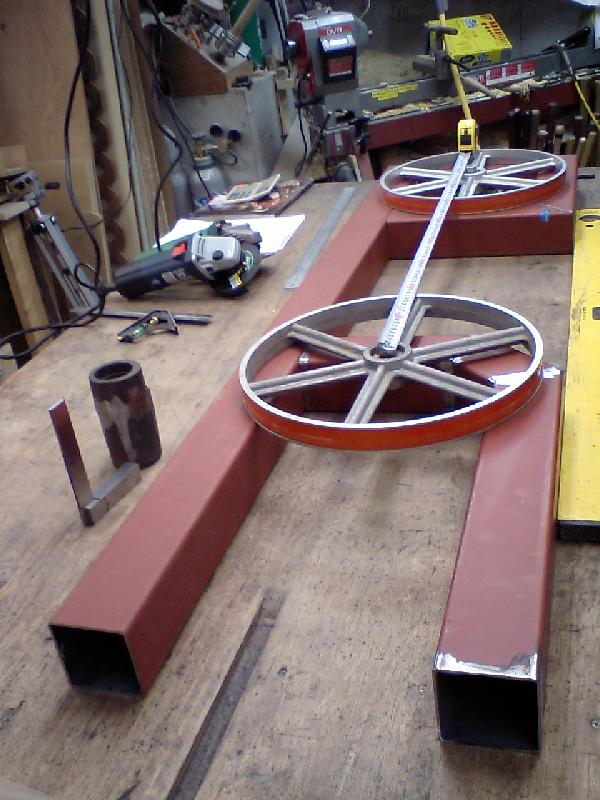
OK, now here I'm getting ready to do some welding, but I have to make sure the
distance between
the two wheel hubs will be what I need to use the 105" bandsaw
blades.
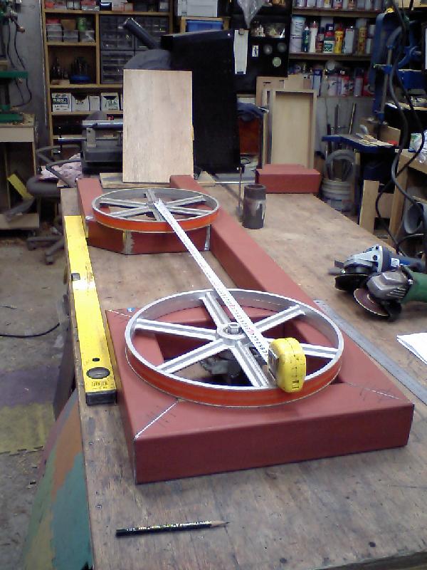
Another look, everything looks good!!
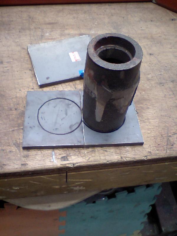
Now, before I start to weld up the frame, I want to make sure the bottom bearing saddle will fit into the frame.
I need to make a cradle of sorts to hold the cast piece the bearings go into..........

This is how it will look, with large holes through the two vertical piece of
plate.....
Laying out where the holes will go.
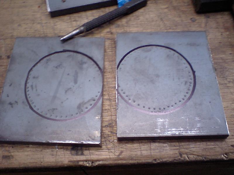
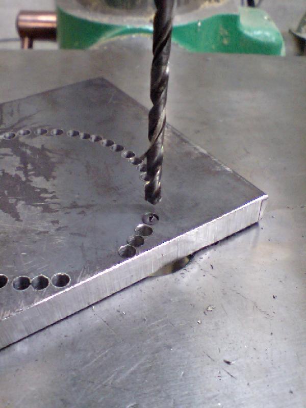
Now I've punched a bunch of holes into the steel to guide the drill bit for the
drill out
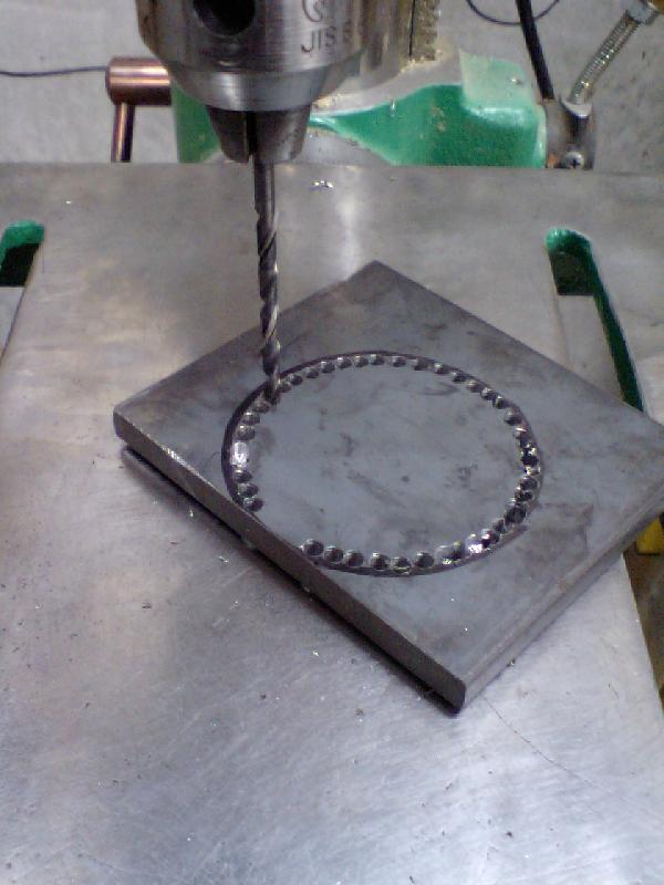
Drilling a bunch of small holes to make a big hole
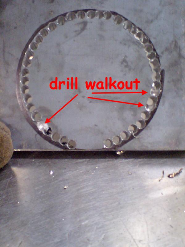
Seems no matter how hard I try, I always get at least a couple of holes that the
drill walks out on.......
Not a big problem, I just flip the piece over and drill it out from the
backside.
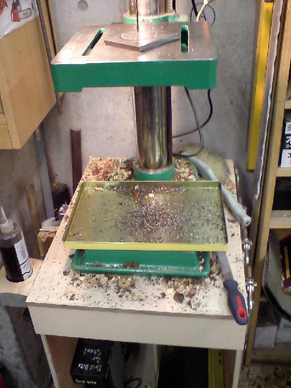
I always put a catch pan below the DP table, to catch all the pieces of steel
and cutting fluid etc, makes clean up easier.
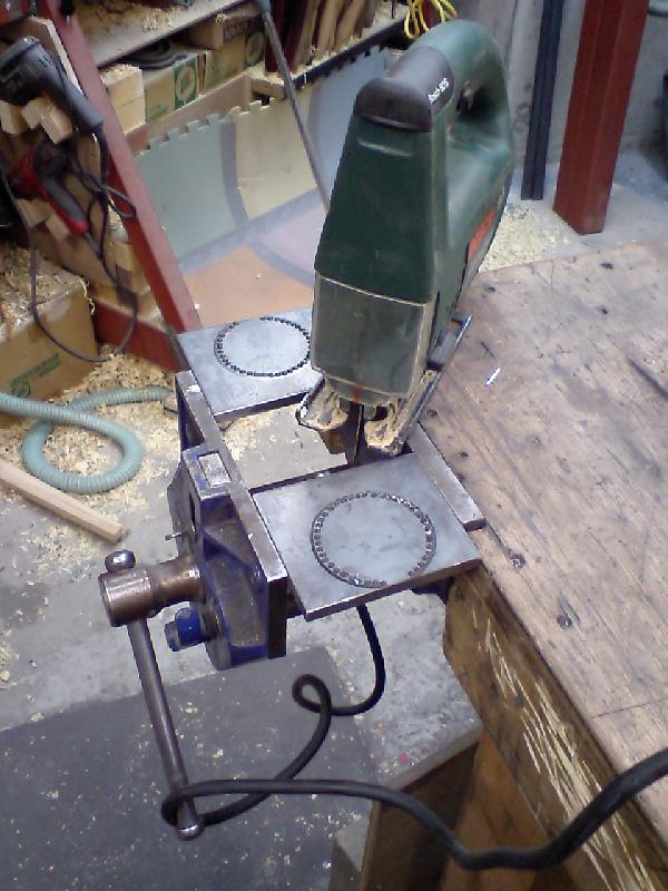
Now that I have the holes drilled it is time to connect the dots......Steel
cutting blade in the Jig Saw.
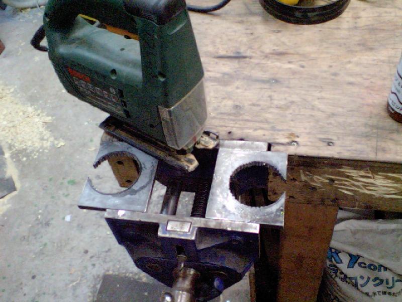
There, a bunch of small holes become big ones!
I then put a large (1" diameter) stone on a mandrel in the drill press and smoothed out the inside of the holes, sorry no pics!
I then fit these to the bearing saddle piece.
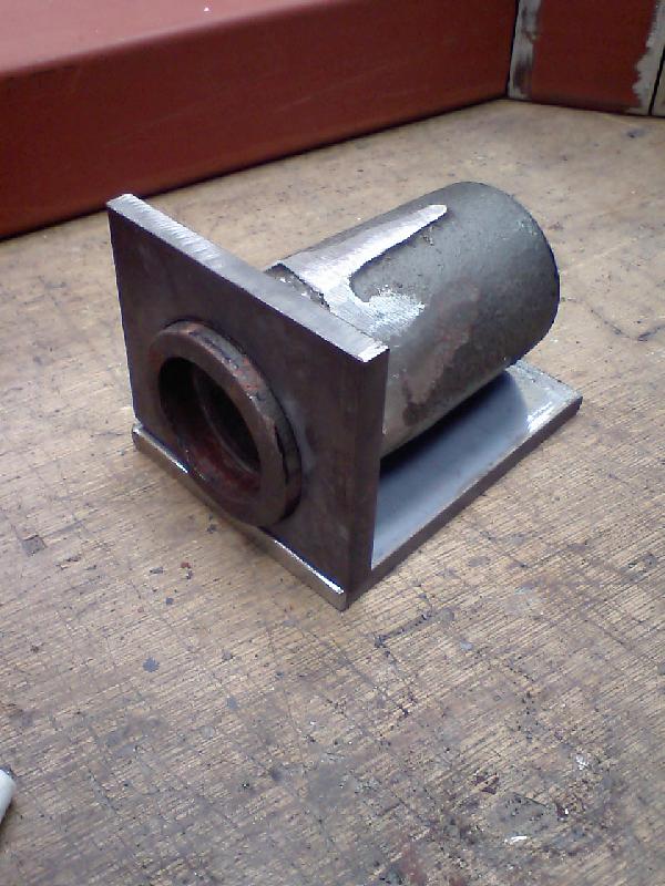
The front one done
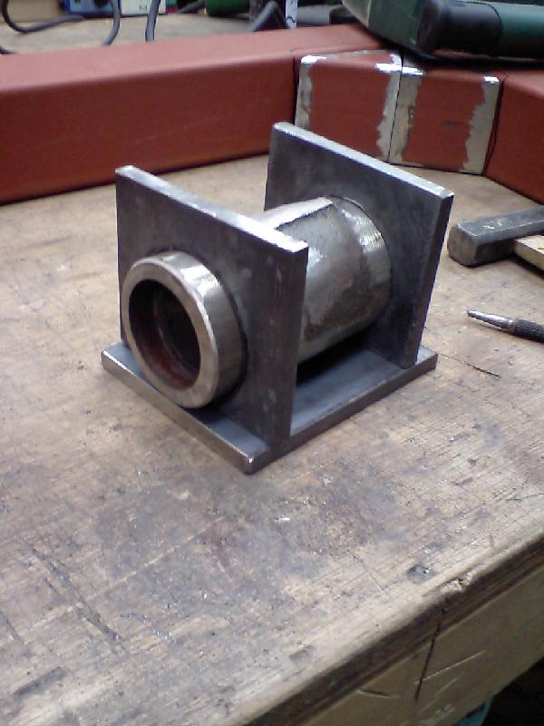
The second one done...
Another view, now I have to weld that sucker up!
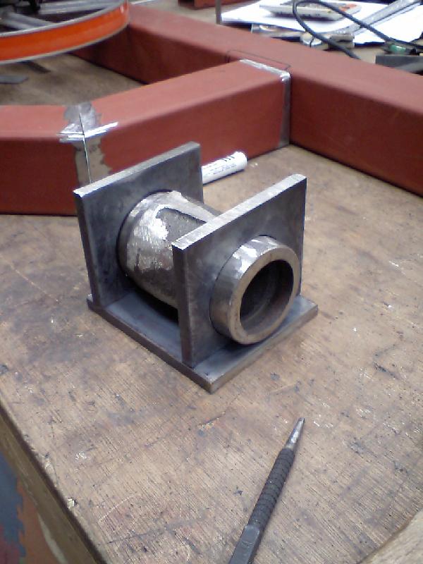
What do you mean you cannot weld Cast Iron???? With a shielded MIG set up you
can!
OK, it is not pretty, but it does work!
(The bearings will be replaced)
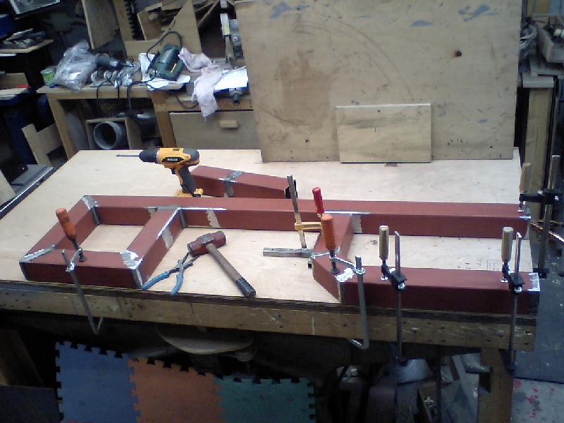
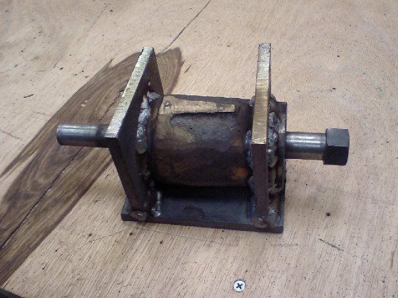
Next was to weld up the frame, here I've welded the top part and I'm setting up
to weld the bottom "H" part.
I put a sacrificial piece of plywood on my workbench top to not burn it up.

All welded!
I know the bottom looks smaller than the top, that is just "Cell
Phone" camera magic...
Next on the list is the top tension/tracking adjuster mech. I
needed some way to "Capture" it in the frame,
and allow it to move up and down to tension the blade.
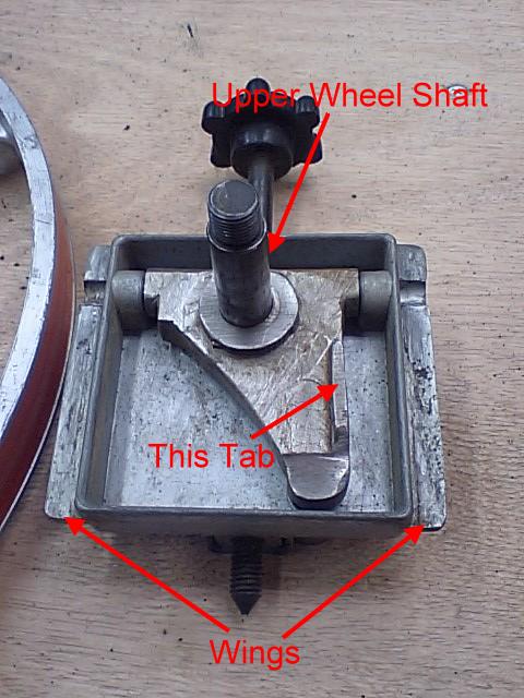
Here is the tension/tracking adjuster. The "Tab" I think is just for strength,
as I see no other purpose for it.
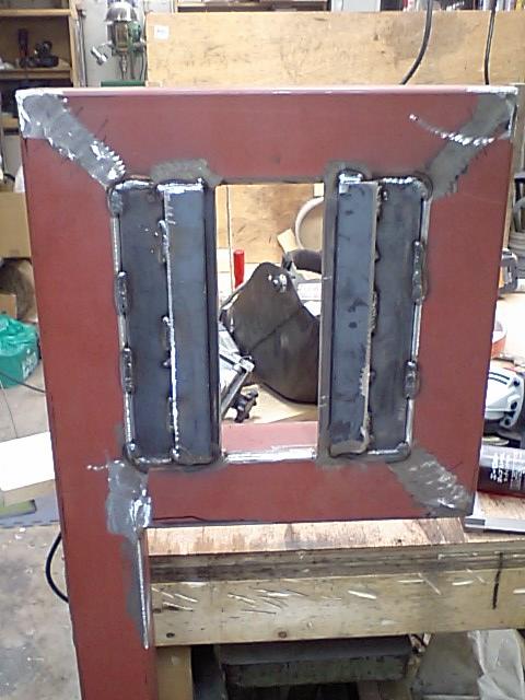
I welded some 1/4" plate into the hole in the top of the frame, leaving
enough room for the tension/tracking adjuster.
The wings will ride up and down between the three plates that are going on
here.....
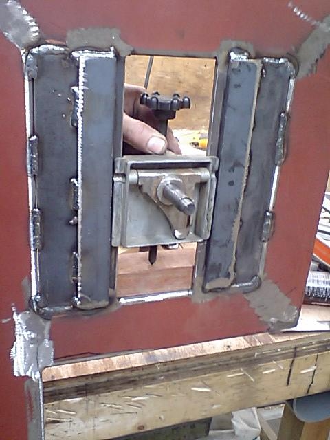
You can see how it fits here.
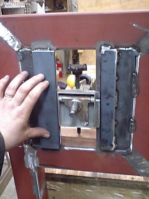
These third plates (one on each side) with capture the wings of the
tension\tracking adjuster,
they will be bolted in place, NOT welded.
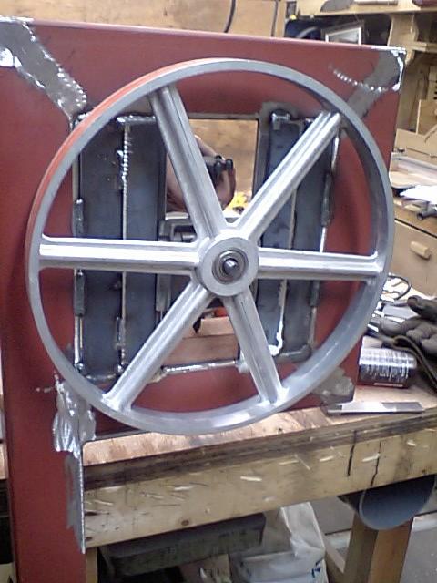
Without the third plates in place, this is how the top wheel will fit up.
I clapped the bottom bearing saddle in place to check the distance between the
wheel hubs, they were right on!
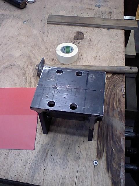
OK, I got the bearing saddle drilled but now I have to transfer the holes to
the frame of the saw.
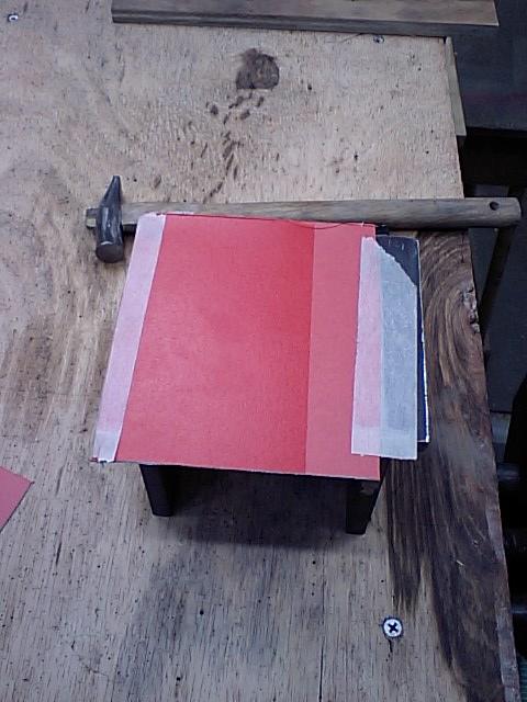
I taped a piece of cardboard onto the bearing saddle, I'll "Tap"
the holes out.
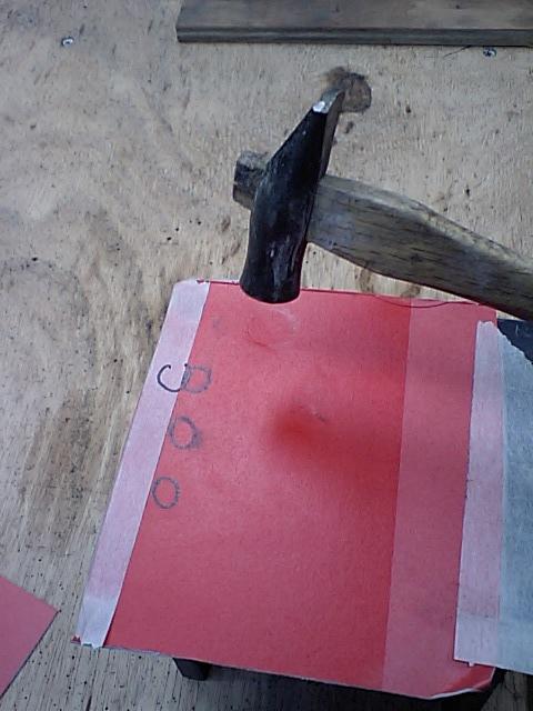
I use the flat face of the hammer to tap the hole, so I can see it
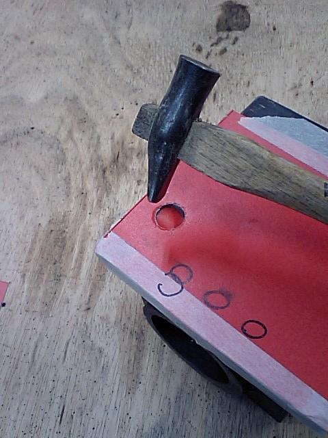
I then use a small hammer and tap out the hole
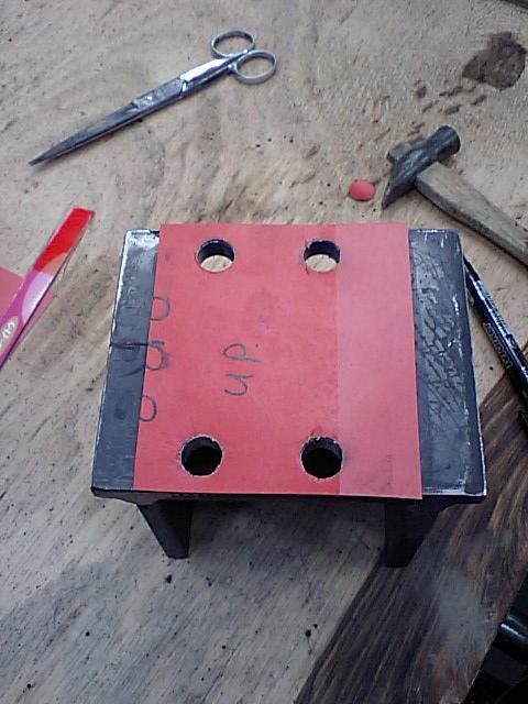
There, all tapped out
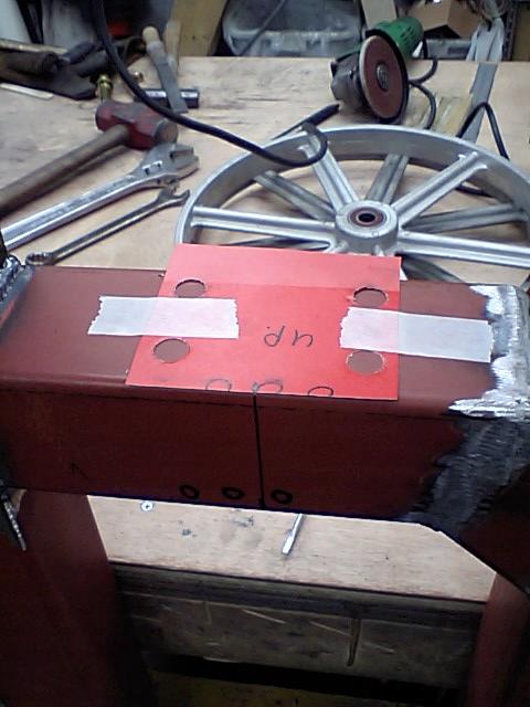
I then use this cardboard template to make the holes on the frame.
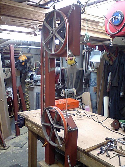
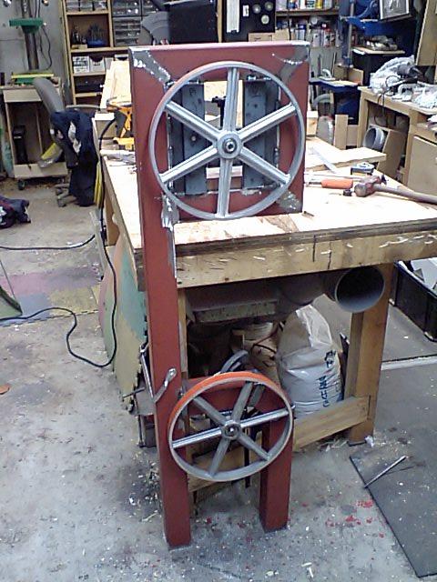
Here is the bottom wheel bolted in place, I'm using a string to mimic the
blade.